We recently got an iRobot Roomba 805 from Costco to help keep up with our dog’s continuous shedding. While it does a pretty good job keeping the floors clean, it has a habit of getting into places it shouldn’t. To that end, iRobot had the forethought to include two devices they call “Virtual Walls” that will tell the Roomba to “swerve” (as my daughter would say) when it gets too close.
Turns out we have quite a few of these forbidden zones and two virtual walls were just not enough, so off I went to Amazon to see if they were sold separately. They were, but for a hefty $50 each! After the initial sticker shock wore off, I thought that it couldn’t be that complicated of a device, and with my admittedly amateur electronics knowledge, I could certainly build one myself for a lot less.
A few quick Google searches later, I found myself on Justin’s DIY Virtual Wall for Roomba project page. Justin does a great job of explaining what these devices do and provides ample detail to DIY, as long as you’re somewhat familiar with PIC microcontrolers. Although I had never worked with the PICs before, I’m lucky enough to have a neighbor that does it for a living and was able to fill in some of the blanks.
Fast forward several hours and a few tasty homebrews later, and my DIY virtual wall was built. While it mostly worked, the Roomba is pretty tenacious about getting where it thinks it wants to go, and on occasion would get by it. I thought there must be something a little off somewhere, so I set out to find out what it was.
Background
The Roomba has a sensor that reacts to infrared (IR) signals sent by various devices, the same way a TV reacts to signals sent by a remote control. Like a TV remote, these IR signals are transmitted on a 38kHz carrier frequency, meaning that when the IR LED is on, it’s actually pulsing on and off 38,000 times per second. Various on/off patterns or “timings” are used to communicate different commands to the Roomba, one of which is used by the virtual wall devices. The PIC’s pulse width modulation (PWM) module is used to generate the carrier frequency on which these patterns are transmitted.
IR Timings
Justin’s project uses IR timing of 1ms on / 1ms off, repeated 100 times, then a gap of about 264ms. As I mentioned, this would not consistently prevent my Roomba from getting past the virtual wall. To verify the IR timings, I connected a TSOP4838 IR detector I had in my parts box to a Raspberry Pi and installed the Linux Infrared Remote Control (LIRC) package. Using LIRC, I was able to see the specific timings for the OEM Virtual Wall that came with my Roomba. These timings came out to be about 500μs on / 7500μs off, repeated three times, followed by a 132ms gap.
Power Consumption
I used the PIC12LF1571 for its “eXtreme Low Power” mode and minimum 1.8V operating voltage (and its support by MCC – more on that below). I also adjusted the resistor values to use as little current as possible and to be compatible with both alkaline (1.5V nominal) and NiMH rechargeable (1.2V nominal) AA batteries. As a result, power consumption is down to about 200μA at 2.4V, which should allow the batteries to last for several months running 24/7. In my testing, I was able to get a comparable distance range to the OEM virtual wall.
Low Battery Indication
I used the PIC’s analog to digital converter (ADC) to monitor the supply voltage and provide a low-voltage indication when it drops below 2.0V. This is done by setting the ADC voltage reference to Vdd and the measurement value to a fixed 1.024V reference. A small amount of math later and we have the actual supply voltage. (Note that values used to determine the supply voltage are multiplied by 1000 to allow the compiler to use integer math instead of incurring the overhead of floating-point math.) Normally LED2 will blink once every 5 seconds to indicate that the virtual wall is active. When a low-voltage condition is detected, the LED will blink twice in each 5-second cycle.
Schematic

This circuit is very similar to Justin’s with the addition of the recommended decoupling capacitors noted in the PIC’s data sheet.
The battery voltage is shown at 2.4V because I am using NiMH rechargeable batteries with a nominal voltage of 1.2V each.
The IR LED (LED1) has a narrow 20° viewing angle to keep the beam as tight as possible over longer distances.
The “heartbeat” LED (LED2) is a low-current (2mA) device driven at about 1mA @ 2.4V to save power.
Bill of Materials
| Part | Ref ID | Vendor | Vendor PN | Qty | Price EA | Price EXT |
|---|---|---|---|---|---|---|
| Box-4x2x1 | Radio Shack | 2701802 | 1 | 2.08 | 2.08 | |
| Circuit board | Radio Shack | 2760148 | 0.25 | 1.30 | 0.33 | |
| PIC 12LF1571 | IC1 | DigiKey | PIC12LF1571-I/P-ND | 1 | 0.66 | 0.66 |
| Socket-8pin | DigiKey | AE9986-ND | 1 | 0.18 | 0.18 | |
| Capacitor-0.1uf | C1 | DigiKey | 445-5303-ND | 1 | 0.30 | 0.30 |
| Capacitor-0.01uf | C2 | DigiKey | 445-5297-ND | 1 | 0.29 | 0.29 |
| Resistor-8.2K | R1 | DigiKey | CF18JT8K20CT-ND | 1 | 0.10 | 0.10 |
| Resistor-68 | R2 | DigiKey | CF18JT68R0CT-ND | 1 | 0.10 | 0.10 |
| Resistor-680 | R3 | DigiKey | CF18JT680RCT-ND | 1 | 0.10 | 0.10 |
| Transistor-NPN-2N3904 | Q1 | DigiKey | 2N3904FS-ND | 1 | 0.18 | 0.18 |
| IR Emitter IR333-A | LED1 | DigiKey | 1080-1080-ND | 1 | 0.44 | 0.44 |
| LED-3mm Red | LED2 | DigiKey | 160-1957-ND | 1 | 0.49 | 0.49 |
| LED Holder-5mm | DigiKey | 492-1503-ND | 1 | 0.23 | 0.23 | |
| LED Holder-3mm | DigiKey | 492-1501-ND | 1 | 0.20 | 0.20 | |
| Battery Holder-2 AA | B1 | DigiKey | BC2AAW-ND | 1 | 1.13 | 1.13 |
| IDC Jumper-F/F | 2 | |||||
| Wire nuts-#22-#16 | 3 | |||||
| Double-sided tape | 2 in. | |||||
| TOTAL | 6.81 |
The Code
I’m using the MPLAB X IDE with the MPLAB XC Compiler to program the PIC. MPLAB X IDE includes the MPLAB Code Configurator (MCC) plugin, which is a GUI configuration tool for most of the more modern PICs. The main C code is below. MCC generates a lot of .c and .h files, so just excerpts of the generated configuration and setup is further below.
When the batteries are inserted, the LED will flash 5 times to let you know it’s working. After that, it will flash once every 5 seconds. The battery is checked for low voltage condition (<2.0V) at each LED flash interval. When 5 consecutive low voltage readings have been detected, the ADC is turned off to save power and the LED will blink twice in each 5-second cycle.
#include "mcc_generated_files/mcc.h"
#define ADC_RES					10			// ADC resolution bits
#define ADC_FVR					1024		// Actual FVR * 1000
#define ADC_ON					(ADCON0bits.ADON = 1)
#define ADC_OFF					(ADCON0bits.ADON = 0)

#define BATT_REF				((long) (1 << ADC_RES) * ADC_FVR)
#define BATT_LOW_V			2000		// 2.000 volts
#define BATT_LOW_CNT		5
#define BATT_LOW_BLINK	1

#define BURST_ON				500			// Burst on duration (uSec)
#define BURST_OFF				7500		// Burst off duration (uSec)
#define BURST_COUNT			3				// How many IR bursts to send

#define BURST_SPACE			132			// 1/31000 * 4096 (clock freq * WDT postscalar) (mSec)
#define CYCLE_MS				(((BURST_ON + BURST_OFF) * BURST_COUNT / 1000) + BURST_SPACE)

#define STARTUP_BLINK   5
#define BLINK_INTERVAL  (5000 / CYCLE_MS)	// About 5 seconds between LED blinks

void init_run(void);
int check_battery(void);

/*
                         Main application
 */
void main(void)
{
  int i;
  int blink_counter = 0;

  // initialize the device
  SYSTEM_Initialize();

  init_run();

  while (1) {
    // Flash the LED and check battery periodically
    if (++blink_counter >= BLINK_INTERVAL) {
      blink_counter = 0;

      // Check battery.  If low, set extra LED blinks
      if (!check_battery()) {
        blink_counter -= BATT_LOW_BLINK;
      }
    }

    // Turn on LED if time to blink
    if (blink_counter <= 0) {
      RA4_SetHigh();
    }

    // Send a few IR bursts
    i = BURST_COUNT;
    while (i--) {
      PWM3_Start();
      __delay_us(BURST_ON);
      PWM3_Stop();
      __delay_us(BURST_OFF);
    }

    // Turn off LED if on
    if (blink_counter <= 0) {
      RA4_SetLow();
    }

    // Then sleep for a moment
    SWDTEN = 1;				// Enable watch dog timer
    asm("sleep");
    SWDTEN = 0;				// Disable watch dog timer
  }
}

void init_run(void) {
  int i;

  // Turn on ADC for battery status
  ADC_ON;

  // Blink the LED at least 5 times until FVR output is ready
  i = STARTUP_BLINK;
  while (i-- || !FVR_IsOutputReady()) {
    RA4_SetHigh();
    __delay_ms(200);
    RA4_SetLow();
    __delay_ms(200);
  }
}

int check_battery(void) {
  int batt_val;
  static int counter = BATT_LOW_CNT;

  // Check battery level if not already flagged as low
  if (counter > 0) {
    // Get battery value.
    // Start AD conversion and wait for it to finish.
    // batt_val is actual voltage * 1000 (for int math)
    ADC1_StartConversion();
    while (!ADC1_IsConversionDone());
    batt_val = BATT_REF / ADC1_GetConversionResult();

    // Battery must be below threshold BATT_LOW_CNT consecutive times.
    // If battery level is above threshold, reset counter.
    // When battery reaches low state, turn off ADC to save power
    if (batt_val >= BATT_LOW_V) {
      counter = BATT_LOW_CNT;
    }
    else if (--counter <= 0) {
      ADC_OFF;
    }
  }

  // Battery has reached low state - return 0
  if (counter <= 0) {
    return 0;
  }

  // Battery has not reached low state - return current counter value
  return counter;
}
Excerpts from the MCC-generated configuration and initialization code are below. MCC generates several source files which are #included in the main source file, and the relevant parts are shown here here to provide the details needed to configure MCC. There are also several MCC-generated helper functions that are used in the main code, so the actual MCC-generated code should be used in the project.
// Initialization code from MCC-generated mcc.c
// Configuration bits: selected in the GUI
// CONFIG1
#pragma config FOSC = INTOSC    // ->INTOSC oscillator; I/O function on CLKIN pin
#pragma config WDTE = SWDTEN    // Watchdog Timer Enable->WDT controlled by the SWDTEN bit in the WDTCON register
#pragma config PWRTE = OFF    // Power-up Timer Enable->PWRT disabled
#pragma config MCLRE = ON    // MCLR Pin Function Select->MCLR/VPP pin function is MCLR
#pragma config CP = OFF    // Flash Program Memory Code Protection->Program memory code protection is disabled
#pragma config BOREN = OFF    // Brown-out Reset Enable->Brown-out Reset disabled
#pragma config CLKOUTEN = OFF    // Clock Out Enable->CLKOUT function is disabled. I/O or oscillator function on the CLKOUT pin
// CONFIG2
#pragma config WRT = OFF    // Flash Memory Self-Write Protection->Write protection off
#pragma config PLLEN = OFF    // PLL Enable->4x PLL disabled
#pragma config STVREN = ON    // Stack Overflow/Underflow Reset Enable->Stack Overflow or Underflow will cause a Reset
#pragma config BORV = LO    // Brown-out Reset Voltage Selection->Brown-out Reset Voltage (Vbor), low trip point selected.
#pragma config LPBOREN = OFF    // Low Power Brown-out Reset enable bit->LPBOR is disabled
#pragma config LVP = OFF    // Low-Voltage Programming Enable->High-voltage on MCLR/VPP must be used for programming

// SCS INTOSC; SPLLEN disabled; IRCF 2MHz_HF;
OSCCON = 0x62;
// TUN 0;
OSCTUNE = 0x00;
// WDTPS 1:4096; SWDTEN OFF;
WDTCON = 0x0E;

// Initialization code from MCC-generated adc.c
// set the ADC1 to the options selected in the User Interface
// GO_nDONE stop; ADON disabled; CHS FVR;
ADCON0 = 0x7C;
// ADFM right; ADPREF VDD; ADCS FOSC/2;
ADCON1 = 0x80;
// TRIGSEL no_auto_trigger;
ADCON2 = 0x00;
// ADRESL 0;
ADRESL = 0x00;
// ADRESH 0;
ADRESH = 0x00;


// Initialization code from MCC-generated fvr.c
// CDAFVR off; FVREN enabled; TSRNG Lo_range; ADFVR 1x; TSEN disabled;
FVRCON = 0x81;


// Initialization code from MCC-generated pin_manager.c
// LATx registers
LATA = 0x00;
// TRISx registers
TRISA = 0x08;
// ANSELx registers
ANSELA = 0x00;
// WPUx registers
WPUA = 0x08;
OPTION_REGbits.nWPUEN = 0;
// ODx registers
ODCONA = 0x00;
// APFCONx registers
APFCON = 0x00;


// Initialization code from MCC-generated pwm.c
// set the PWM3 to the options selected in the User Interface
//PHIE disabled; DCIE disabled; OFIE disabled; PRIE disabled;
PWM3INTE = 0x00;
//PHIF cleared; OFIF cleared; DCIF cleared; PRIF cleared;
PWM3INTF = 0x00;
//PS No_Prescalar; CS FOSC;
PWM3CLKCON = 0x00;
//LDS reserved; LDT disabled; LDA do_not_load;
PWM3LDCON = 0x00;
//OFM independent_run; OFS reserved; OFO match_incrementing;
PWM3OFCON = 0x00;
//PWM3PHH 0;
PWM3PHH = 0x00;
//PWM3PHL 0;
PWM3PHL = 0x00;
//PWM3DCH 0;
PWM3DCH = 0x00;
//PWM3DCL 26;
PWM3DCL = 0x1A;
//PWM3PRH 0;
PWM3PRH = 0x00;
//PWM3PRL 52;
PWM3PRL = 0x34;
//PWM3OFH 0;
PWM3OFH = 0x00;
//PWM3OFL 1;
PWM3OFL = 0x01;
//PWM3TMRH 0;
PWM3TMRH = 0x00;
//PWM3TMRL 0;
PWM3TMRL = 0x00;
//MODE standard_PWM; POL active_hi; OE enabled; EN disabled;
PWM3CON = 0x40;
The Build
The circuit board I used is just the right size to be cut into 4 pieces, each piece just the right size for all of the components and fits almost perfectly in the slots in the project box. I used a Dremel with a cutting wheel to get a smooth cut. Small notches were made in the outer corners of the board to allow the ridge of the enclosure cover to seat properly.

This is the front and back of the completed circuit board. I used two 2-pin IDC terminals to attach the LEDs to the board. The two green wires are for a small slide switch I was going to include, but I couldn’t find a good way to cut a small rectangular hole for it. With the batteries lasting as long as they do, it’s probably not necessary anyway.
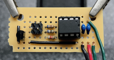

IDC socket leads were soldered to the LED leads and insulated with heat shrink tubing. I used 10cm female/female jumpers cut in half and trimmed to length.

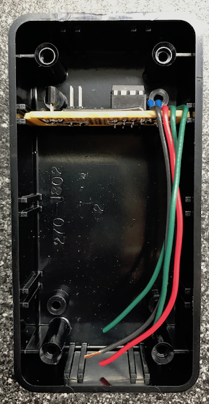
The two lower mounting bosses in the enclosure needed to be removed in order for the battery holder to fit. I used a small wood chisel at the base, and with a little work they popped right off. The battery holder is affixed to the inside of the enclosure with high-strength double-sided tape. I used 3M VHB 5952 tape (strong stuff), but just about any double-sided tape should work.
I also put a small piece of electrical tape on the top of the battery holder to prevent the circuit board from accidentally shorting against the exposed battery terminals (yes, it happened once).


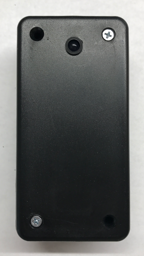
The IR LED is mounted with the 5mm holder in a 1/4 inch hole toward the top of the plastic cover. The depth of this holder will keep the IR LED flush with the box cover and help to narrow the beam a little. The heartbeat LED is mounted with the 3mm holder in a 5/32 inch hole in the top of the enclosure.


The completed circuit board slides into the slots at the top of the enclosure. If you’re using another enclosure that doesn’t have slots, you can use another piece of double-sided tape to affix the board to the back of the enclosure as well.

Wrapping It Up
Similar to Justin’s build, the parts come in at around $8, including the jumper wires, small strip of double-stick tape and small wire nuts. This was my first time using a PIC MCU, and luckily I was able to borrow my neighbor’s ICD 3 In-Circuit Debugger to program the chip and debug the code, so I didn’t have that added expense.
I tested the low-voltage detection code using my Rigol power supply, lowering the supply voltage from 2.05V by 0.01V and waiting the 5 cycles each time until the LED double-flashed. This consistently happened at 2.00 – 2.01V. I was expecting it to happen at 1.99V, but I don’t know how precise the power supply and ADC are down to hundredths of a volt.
With the new IR on/off timings, my Roomba does a quick about-face as soon as it reaches the beam. I’ve also seen the Roomba it do its “corner detection dance” at the virtual wall (those of you that have a Roomba know what I’m talking about) and it turned away every time, where the old timings would sometimes allow it to break through.
The DIY unit doesn’t have the “halo mode” that the OEM units have, but the wall mode works for the additional areas that I have so that’s not an issue. Halo mode uses an upward-facing IR LED pointed at a conical reflector to cast the IR beam in a circle pattern around the device. This might be an opportunity for a “Version 2” using a 3D printer and some mirror-finish paint.
Click here to download a ZIP file containing all of the MPLAB X code used in this project.
This looks fantastic! Great idea about using the RaspberryPi for the IR timings. I also love the halo idea with the 3d printer.
Thanks for the comment Justin – and thanks for the great work on your virtual wall!
Hi Greg,
This is amazing. Great looking finished project. And kudos to Justin as well. I am also in need of several virtual walls. I am pretty handy with soldering and following a diagram, but have no experience programming. Is there any possibility someone could purchase a few (3) programmed PICs? Thanks.
Steve
Could you build this in a single gang new work electric box for a built in approach
I would probably use a plastic box as opposed to a metal one so nothing gets shorted, but other than that I don’t see why not.
Hey Greg – any idea if the Curiosity Dev Board (digikey PN DM164137-ND) will program the PIC? $22 vs $200 for the ICD 3 debugger is significant.
Hi Rob – Not sure about the board you mention – I’ve only ever used the ICD3. I believe the PICKITs can program these MCUs – they’re available on Amazon starting around $20 depending on the functionality you want.
Thanks Greg. I scored an Arduino for Xmas, so I ended up going with an ATtiny45 instead of the PIC and using the Arduino as a programmer. Works perfectly keeping my roomba where it belongs. Thanks so much for providing the IR timings here – couldn’t have done it w/o them.
Any chance you could share your MPLAB project for this? I’ve mostly recreated it, but I think some of the pin configuration/etc is maybe not identical between versions, so the registers shown don’t recreate the same behavior.
Do you know which files from the project you need, or just all of them under in the project directory? I can zip them up and email to you if you like.
The whole project would probably be ideal, but also just the .mc3 file to re-generate from I think would work. My version of MCC complains about this particular set of pin configuration register values when I try to work backwards from the final registers you have in pin.c. The PWM timing also seems to be slightly off, but I think that part is within tolerances.
Link to project files added to end of post.
Thank you so much for the detailed write-up! Since you’ve offered, could you please email or host all the MPLAB project files somewhere? It would be much appreciated. I’m looking forward to building a few of these myself and just want to be sure I’m not missing anything.
Thanks again!
Link to project files added to end of post.
Hi,
I’m trying to compile the project, but keep getting errors.
maybe you can add explanation how you compiled the code.
Thanks,
Nadav
Hi,
please help with the compiler.
I’m getting many errors
Thanks
The parallel bypass caps must be an error. Either the .01 is redundant or should be connected to a different pin.
From the PIC data sheet: “To ensure these oscillator frequency tolerances, VDD and VSS must be capacitively decoupled as close to the device as possible. 0.1 uF and 0.01 uF values in parallel are recommended.”
Greetings fellow internet traveller! I was just building your project and had some comments and suggestions.
This is my first PIC programming experience, and I’m a beginner at both electronics and C++, so I wanted to provide feedback from a newbie’s point of view.
1) I think the PIC schematic is shown “feet up”, that was very confusing. Your diagram did not look like mine. With “feet down”, and the notch left, PIN1 should be directly below the notch.
2) I love the MCC Generated files, you had included PWM3.c/h, but I wanted to have my IR on PWM1, so a quick find-and-replace and it’s easy to have PWM1.c/h and PWM2.c/h for my next project.
3) I am REALLY lost on how you are checking voltage. My goal was to build out the ADC and provide options to use AN0-AN3. I am using a TP4096 in front of my LiPo battery (which always sends 4.2V, so I wanted to send B+ (the actual battery positive lead, which can degrade) to AN0. Unfortunately, that’s where I’m a little lost. Can you assist?
4) Another person mentioned timings were a bit off, and it feels that way. I don’t get a 100% success rate at the wall. Is it because I’m using a higher voltage (4.2V vs. 2.4V as in your diagram?)
I appreciate the write up both you and Justin did, especially the “how to level up” part of this project. $200 later (after a Pickit and all the parts), and my $8 Virtual Wall is well worth the investment! I learned more here than I did in some classes at university. Thank you.
Hi Justin,
Thanks for your comments.
The schematic was off because I apparently flipped the PIC horizontally instead of rotating it. I fixed the image so it’s correct now.
Without going into more detail than is in the post, you can try googling “checking battery voltage with PIC ADC”. There should be several hits that explain how this works in more detail.
The timings were correct for my Roomba as mentioned in the post and it stops mine every time. If yours is not the same model, you may want to check your timings as I have described. I don’t think the higher voltage is a problem for the timings, but you might want to adjust the resistor values accordingly.
Thank you for responding. Yes, after a month of weekend playing around, I finally figured it the issues from my first post. There were no timing issues, I had interference. Also, I was way off on my ADC statement (paragraph 3), a lot of bad assumptions, basically just ignore it from my first post. The whole post is a huge #mybad.
I figured out the circuit required for the LiPo battery monitoring; both an MCP1700 LDO Voltage Regulator (I chose 3.3v) on the output from the TP4056 and a voltage divider circuit (R1=22k, R2=68k) on the battery positive helped complete the monitoring.
A word of caution for users wanting to “play” with this code. The MCC Code Generator makes a LOT of extra code, and the XC8 compiler stopped optimizing floats. Right in the middle of a coding session, I started getting “Can’t find words for psect in segment” errors, indicating I was out of memory for my application to my chip.
Two helpful hints for optimizing code: (1) there are tens of functions that are unused from MCC generated code, you can delete them from the C and H files, they are there for (2) the default floating point math in XC8 2.05+ is 32-bits, avoid at ALL costs.
Regarding (2), you were probably compiling under a pre-2.0 version of XC8, which uses 24-bit words for math, so `BLINK_INTERVAL` and `batt_val` are now taking up more memory than necessary. I solved that by statically setting `BLINK_INTERVAL` to 33 (5000/150) and I pre-calculated the math for `batt_val` and used the raw ADC (0-1024) values for comparison (eliminating `BATT_LOW_V`). Even with integer math, I was running out of memory when the divisor has decimal points. Alternatively, one could set the compiler options for the project to use C90, and 24-bit doubles and floats for a bit of extra room.
For a LiPo monitoring circuit, to get the actual battery voltage converted from ADC, the formula is: ADC_value * 1000 (for four digits and to drop the decimal) / 1024 (to get percentage of ADC) * 3.3 (the value of the regulator) * (R1 + R2) / R2. The known values all crunch down to 4.265280331. But even multiplying ADC by 4.0 gives me an out of memory error. As soon as you add that decimal point, things get crazy. So, I opted to put my big-boy pants on and work out the “low battery voltage” as an ADC value and put that in Line 107, without the math conversion from Line 102 (from the above code). In my case, when a 3.7V LiPo battery hits 844 (~3.6V), start blinking that red light. Different batteries have different voltage curves!
Thanks, again!
I used an arduino using the IR library to test the timings on a new Dual Mode Virtual Wall.
I got 500/7500/500/750/500/7500 and then roughly 40-50ms, not the 132 that you reported.
Also, halo mode seemed to be the same protocol as the regular wall mode, though I think they put in a separate LED.
Having never soldered anything to circuit board and having no experience with PICs, I still managed to successfully build this in an afternoon. It seems to work perfectly! Now I may make a few more for areas where my Roomba gets stuck
What an awesome project! 🙂 Thanks very much for doing this work and for posting this! I learned A LOT!
Super fun and it works like a charm!
…now to find more fun PIC projects!